Just-Fit Ball Reducer JFR series

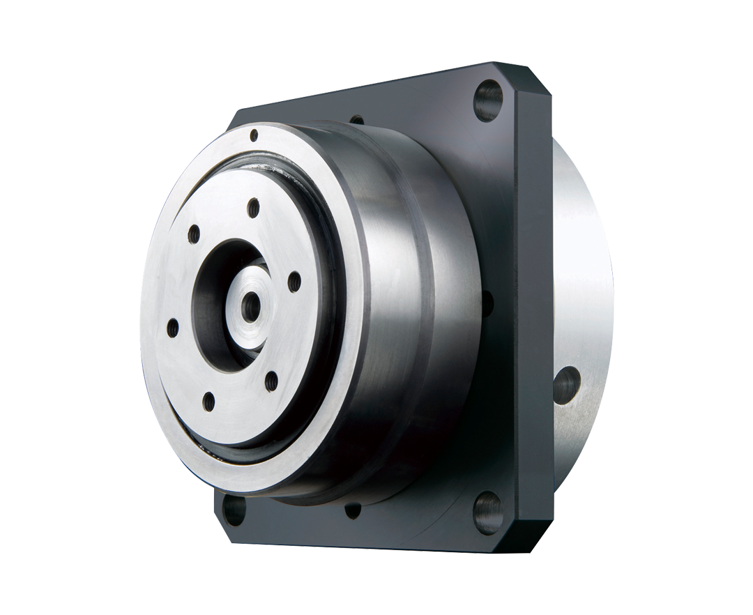
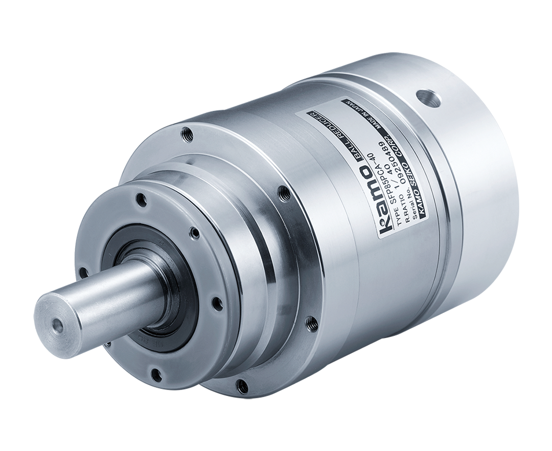
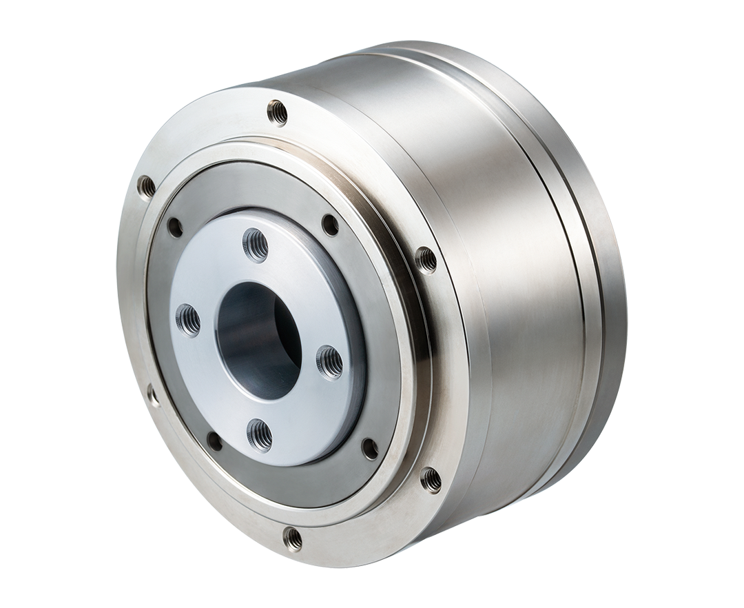
A flange-type Ball Reducer with a thin output section.
Its dedicated integrated crossed roller bearing in the output shaft enables the machine to handle high loads despite its low profile.
This model is 30% to 50% thinner than the conventional Ball Reducer.
Technical InformationHighlights
-
Thin Design
Its output shaft support uses a thin crossed roller bearing to achieve a thin profile and meet the design’s space-saving requirements.
-
Zero-Backlash
Uses a steel ball in the deceleration mechanism instead of a gear. Eliminates backlash and enables prevision feeding and high-precision positioning through constant rolling contact via preload.
-
Compact & Simple
Uses a steel ball in the deceleration mechanism instead of a gear. Eliminates backlash and enables prevision feeding and high-precision positioning through constant rolling contact via preload.
-
Motor Attachment Standardization
The JFR Series has standardized motor attachments for servo motors of various manufacturers, allowing the motor to be immediately installed after purchase.
-
Maintenance-free
Its grease-filled reducer can be used without lubrication for its entire rated life. Also has no mounting position restrictions.
-
High Efficiency
Its transmission mechanism achieves a high-efficiency drive using a large number of steel balls.
Model
Thin Ball Reducer
- JFR
- 1
- 60
- 2
- S
- 3
- C
- 4
- A
- 08
- 7
- 1. Product Name
- JFR series
- 2.Frame number
- 60、90、120
- 3.Output shaft shape
-
S: Shaft output
U: Flange output
- 4.Input shaft shape
- C: Clamp
- 5.Reduction ratio
- 10.5, 15, 20, 30, 40 (Frame number 90, 120 only)
- 6.Motor mounting code
-
Please refer to the dimensional drawing or the motor and reducer compatibility table.(Catalog: P10-16)
- 7.Input shaft hole diameter
-
Please refer to the specification table or external dimension drawing.(Catalog: P9-12)
- 8.Output shaft option (only for S type)
-
A:Standard
B:With keyway
C:Tip tap
D:With keyway + Tip tap
Specifications
| Model |
|---|
| JFR60 | JFR90 | JFR120 | |||||||||||
|---|---|---|---|---|---|---|---|---|---|---|---|---|---|
| Reduction ratio | ||
|---|---|---|
| Rotation direction(Rotation direction of output shaft correlated to input shaft) | ||
| Allowable rated torque | N・m | |
| Acceleration peak torque | N・m | |
| Max. instantaneous torque | N・m | |
| Allowable average number of input revolutions | rpm | |
| Max input rpm | rpm | |
| Recommendable motor capacity | W | |
| Inertia moment converted to input shaft | Output shaft U-shaped type | ×10-4kg・㎡ |
| Output shaft S-shaped type | ||
| Input shaft hole diameter | ㎜ | |
| Outline drawing (U type, S type) | ||
| CAD Data | ||
| Catalog | ||
| Instruction Manual | ||
| 10.5 | 15 | 20 | 30 | 10.5 | 15 | 20 | 30 | 40 | 10.5 | 15 | 20 | 30 | 40 |
| Reverse | Reverse | Reverse | |||||||||||
| 8.5 | 9.4 | 10.4 | 10.5 | 25.9 | 28.5 | 30.8 | 30.5 | 29 | 63.4 | 70 | 81.4 | 77.5 | 72.3 |
| 25.5 | 27.9 | 31.2 | 29.6 | 77.7 | 81 | 81.7 | 91.5 | 87 | 190.2 | 210 | 244.2 | 232.5 | 198.5 |
| 50 | 180 | 450 | |||||||||||
| 3000 | 3000 | 3000 | |||||||||||
| 4500 | 4500 | 4500 | |||||||||||
| 200 | 400 | 750 | |||||||||||
| 0.152 | 0.153 | 0.154 | 0.155 | 0.655 | 0.659 | 0.667 | 0.672 | 0.677 | 2.660 | 2.660 | 2.690 | 2.710 | 2.740 |
| 0.154 | 0.15 | 0.155 | 0.155 | 0.664 | 0.664 | 0.669 | 0.673 | 0.677 | 2.720 | 2.69 | 2.700 | 2.720 | 2.750 |
| 14 | 19 | 24 | |||||||||||
| 11 | 16 | 22 | |||||||||||
| 8 | 14 | 19 | |||||||||||
| – | 11 | 16 | |||||||||||
| – | 10 | 14 | |||||||||||
| – | 8 | – | |||||||||||


