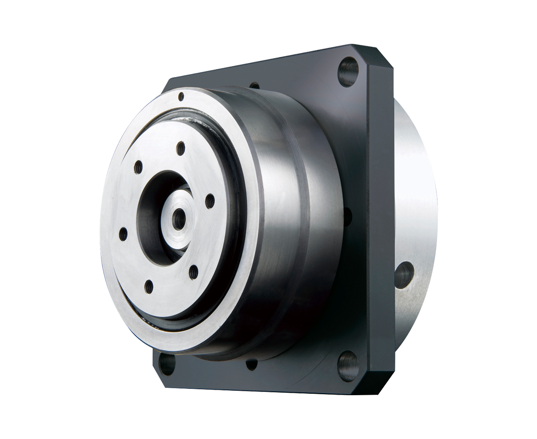
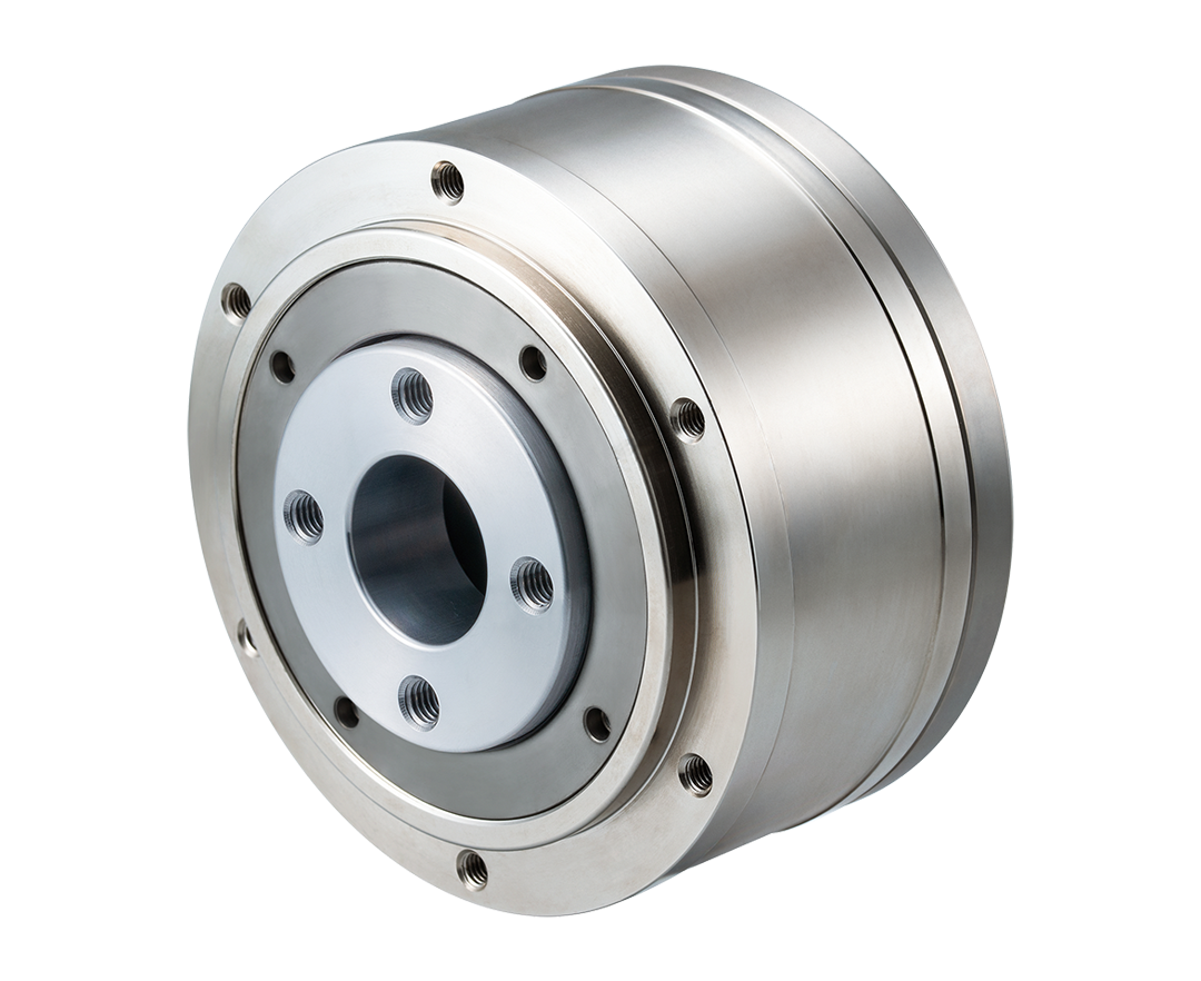
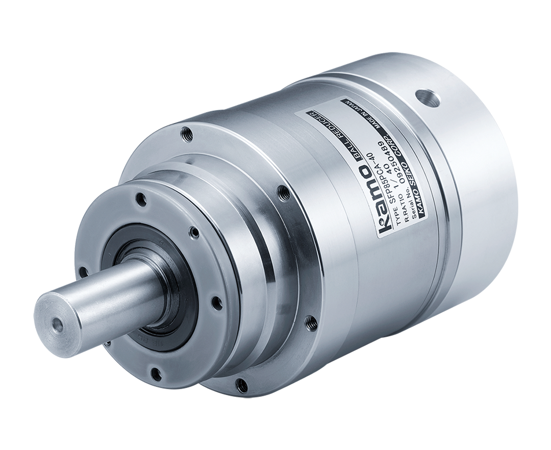
Reinformed Ball Reducer SFP series
A Ball Reducer featuring increased allowable torque due to its improved cycloid curve in the torque transmission section, its allowable radial load has also been enhanced by using three-point support for its output shaft bearing.
Technical InformationHighlights
-
Improved Load Capacity
Boasts improved allowable radial load of the output shaft and enhanced rigidity, with every component upgraded based on the BR Series.
-
Zero-Backlash
Uses a steel ball in the deceleration mechanism instead of a gear. Eliminates backlash and enables prevision feeding and high-precision positioning through constant rolling contact via preload.
-
Compact & Simple
Has a reduction mechanism and input/output bearings built into its housing for compactness and ease of installation.
-
Motor Attachment Standardization
The SFP Series has standardized motor attachments for servo motors of various manufacturers, allowing the motor to be immediately installed after purchase.
-
Maintenance-free
Its grease-filled reducer can be used without lubrication for its entire rated life. Also has no mounting position restrictions.
-
High Efficiency
Its transmission mechanism uses a large number of steel balls to achieve a high-efficiency drive. The rolling contact of the balls is similar to that of a ball screw, allowing extremely light operation and maximized capacity of any motor.
Model
Roller Pinion
- SFP
- 1
- 70
- 2
- S
- 3
- C
- 4
- A
- 08
- 7
- 0
- 0
- A
- 9
- 0
- 10
- 1. Product Name
- SFP series
- 2.Frame number
- 70、85、100、125
- 3.Output shaft shape
- S: Shaft output
- 4.Input shaft shape
- C: Clamp
- 5.Reduction ratio
- 8 (70 only), 10, 20, 30, 40, 50 (125 only)
- 6.Motor mounting code
Please refer to the dimensional drawing or the motor and reducer compatibility chart.(Catalog: P20-21, 23-25)
- 7.Input shaft hole diameter
Please refer to the specification table or dimensional drawing.(Catalog: P19-21)
- 8.Output shaft diameter
- 16(70 only)、20(85 only)、25(100 only)、30(125 only)
- 9.Output shaft option
-
A:Standard
B:With keyway
C:Tip tap
D:With keyway + Tip tap
- 10.Mounting plate
-
F:Available
0:None
Specifications
| Model |
|---|
| SFP70SCA | SFP85SCA | SFP100SCA | SFP125SCA | |||||||||||||
|---|---|---|---|---|---|---|---|---|---|---|---|---|---|---|---|---|
| Reduction ratio | |
|---|---|
| Rotation direction(Rotation direction of output shaft correlated to input shaft) | |
| Allowable rated torque | N・m |
| Acceleration peak torque | N・m |
| Maximum instantaneous torque | N・m |
| Allowable radial load at output shaft *1 | N |
| Allowable thrust load at output shaft *1 | N |
| Allowable average number of input revolutions | rpm |
| Max input rpm | rpm |
| Inertia moment converted to input shaft | ×10-4kg・㎡ |
| Recommendable motor capacity | W |
| Input shaft hole diameter | ㎜ |
| Outline Drawing | |
| CAD Data | |
| Catalog | |
| Instruction Manual | |
| 8 | 10 | 20 | 30 | 10 | 20 | 30 | 40 | 10 | 20 | 30 | 40 | 10 | 20 | 30 | 40 | 50 |
| Reverse | Forward | Reverse | Forward | Reverse | Forward | Reverse | Forward | |||||||||
| 10 | 11 | 12 | 12.8 | 25.5 | 28.4 | 26.2 | 26 | 48.8 | 56 | 56 | 56 | 90 | 96.5 | 96.5 | 98.8 | 99.2 |
| 20 | 21.2 | 22 | 22.6 | 42 | 48.3 | 44.6 | 44.2 | 78 | 89.4 | 95.2 | 95.2 | 155 | 168.9 | 168.9 | 172.9 | 173.6 |
| 40 | 70 | 85 | 130 | 160 | 240 | 270 | ||||||||||
| 500 | 1000 | 1500 | 2000 | |||||||||||||
| 200 | 400 | 600 | 1000 | |||||||||||||
| 3000 | 3000 | 2000 | 2000 | |||||||||||||
| 4500 | 4500 | 4000 | 4000 | |||||||||||||
| 0.149 | 0.149 | 0.159 | 0.161 | 0.484 | 0.431 | 0.414 | 0.406 | 1.58 | 1.43 | 1.38 | 1.36 | 3.45 | 2.98 | 2.86 | 2.81 | 2.78 |
| 200 | 200 | 100 | 100 | 400 | 200 | 200 | 100 | 750 | 400 | 400 | 200 | 1500 | 750 | 750 | 400 | 400 |
| 14 | 14 | 19 | 24 | |||||||||||||
| 11 | 11 | 16 | 22 | |||||||||||||
| 8 | 8 | 14 | 19 | |||||||||||||
| – | – | 11 | 16 | |||||||||||||
| – | – | – | 14 | |||||||||||||
*1 This allowable radial load value is realized when the load positioned in the axial direction is the figure at top of shaft.